
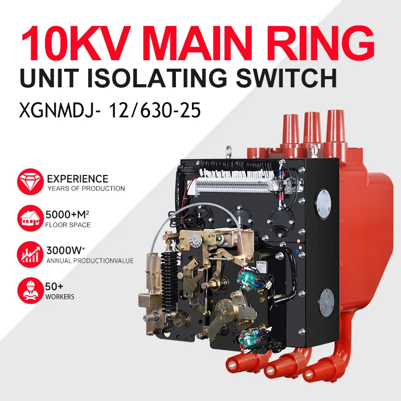
Vacuum Circuit Breaker Contacts – Complete Technical Guide 2025
The following is the table of contents for this article.
Thanks for sharing the article.
Vacuum Circuit Breaker Contacts
Introduction to Vacuum Circuit Breaker Contacts
Vacuum circuit breaker (VCB) contacts are the core components responsible for interrupting short-circuit and load currents inside a vacuum interrupter. When a VCB opens, the contacts separate and an arc forms inside the vacuum. The arc is quickly extinguished because the vacuum environment eliminates gas ionization. Because of this unique behavior, the performance, material, shape, and durability of VCB contacts directly determine the reliability and lifetime of the entire vacuum circuit breaker.
Contacts are engineered with extreme precision—typically micron-level tolerances—because small deviations affect dielectric strength, contact resistance, and arc behavior. For medium-voltage systems from 3.6 kV to 40.5 kV, VCB contact design is one of the most sophisticated aspects of switchgear engineering.
Importance of VCB Contacts in Circuit Interruption
VCB performance is determined by:
Contact material
Contact shape and geometry
Contact resistance
Erosion resistance
Thermal stability
Ability to distribute and control arc
During a short-circuit event, contacts must withstand high temperature, extreme electromagnetic forces, rapid temperature cycling, and mechanical stress. If contact quality is poor, the breaker may fail to interrupt properly, causing catastrophic equipment damage.
Structure of VCB Contacts
Inside a vacuum interrupter, contacts typically include:
Fixed contact
Moving contact
Contact plate/disc
Arcing contact
Contact carrier
Bellows assembly
Shielding system
The moving contact is connected through the bellows, which allows motion while maintaining vacuum integrity.
Contact Materials Used in VCBs
The most widely used material is Copper-Chromium (CuCr) alloy.
Advantages of CuCr:
| Feature | Benefit |
|---|---|
| High melting point | Survives arc heating |
| Low erosion | Long operational life |
| Excellent conductivity | Low temperature rise |
| Stable vacuum behavior | Low arc energy |
| Good mechanical strength | Withstands short-circuit forces |
CuCr is used in 95% of modern VCBs.
Types of VCB Contacts
Common VCB contact structures include:
Spiral Contacts
Generate magnetic arc rotation, preventing hotspots.
Axial Magnetic Field (AMF) Contacts
Used in high short-circuit duty; provide strong axial arc motion.
Radial Magnetic Field (RMF) Contacts
Balance arc movement and erosion; used in medium-duty breakers.
Flat Contacts
Used rarely; suitable for small load interrupters.
Plum Blossom Contacts
Multi-petal structure; improves arc distribution and reduces wear.
How Arc Control Works Inside a VCB
Arc control is central to VCB design. When contacts open:
An arc forms in metal vapor.
Magnetic fields distribute and rotate the arc.
The arc energy reduces.
The current reaches zero.
Vacuum extinguishes the arc instantly.
Arc motion ensures even surface erosion and stable operation.
Contact Resistance and Its Significance
Typical contact resistance: 20–50 micro-ohms.
High resistance causes:
Overheating
Contact welding
Loss of conductivity
Thermal runaway
Regular monitoring is essential.
VCB Contact Erosion Mechanisms
Erosion occurs due to:
Arc heat
Metal vaporization
Pitting
Mechanical friction
Excessive erosion reduces lifespan and increases risk during fault breaking.
Measuring Contact Erosion
Technicians measure erosion using:
Depth gauges
Wear marks
Contact stroke measurements
Gap indicators
Maximum allowable erosion is typically 1–3 mm.
Thermal Performance of Contacts
Contacts must handle:
Continuous current
Short-time withstand current
Peak short-circuit current
Good thermal design prevents deformation and loss of conductivity.
Mechanical Behavior During Operation
Contacts must withstand:
Repeated operations
Mechanical shock
Vibration
Spring stress
Misalignment or insufficient pressure leads to failure.
Contact Gap and Stroke Requirements
Typical gaps:
12 kV → 8–12 mm
24 kV → 10–18 mm
40.5 kV → 18–25 mm
Proper gap ensures dielectric strength.
Contact Wipe (Contact Pressure)
Contact wipe ensures:
Low resistance
Proper heat dissipation
Stable arc behavior
Improper wipe causes overheating and occasionally welding.
Breakdown Voltage Between Contacts
Typical withstand values:
| Voltage Class | Power Frequency | Lightning Impulse |
|---|---|---|
| 12 kV | 28 kV | 75 kV |
| 24 kV | 50 kV | 125 kV |
| 40.5 kV | 95 kV | 185 kV |
Clean contact surfaces improve withstand levels.
Silver Plating and Surface Treatment
Silver plating enhances:
Conductivity
Surface stability
Assembly handling
However, arc resistance depends on the CuCr base.
Wear Indicators on Contacts
Wear indicators show:
Remaining life
Safe operation limits
Replacement timing
Easy visual identification helps maintenance planning.
Testing of VCB Contacts
Key tests include:
Contact resistance test
Mechanical timing test
Vacuum integrity test
Partial discharge test
High-voltage withstand test
These ensure reliable breaker performance.

Contact Failure Modes
Common modes include:
Welding
Excessive erosion
Misalignment
Cracks
High resistance
Each impacts safety and reliability.
Welded Contacts
Welding results from:
High fault energy
Low contact pressure
Poor material quality
Usually requires interrupter replacement.
Poor Arc Movement
Poor arc mobility causes:
Localized erosion
Higher thermal stress
Shortened contact life
Proper magnetic design resolves this.
Reconditioning and Polishing
Minor surface roughness can be improved, but:
Deep erosion
Misalignment
Metal loss
require full VI replacement.
Contact Life Expectancy
Typical lifetime:
| Application | Mechanical Life |
|---|---|
| Industrial | 10,000 ops |
| Utility grade | 20,000+ ops |
| Motor switching | Variable |
| High-fault regions | Shorter |
Life depends on switching frequency and fault energy.
Contact Material Innovations
New developments include:
Advanced CuCr alloys
AMF-optimized geometry
3D laser-cut patterns
Nanostructure reinforcement
These improve erosion resistance and dielectric strength.
Role of Embedded Pole Technology
Embedded poles improve:
Insulation strength
Mechanical stability
Moisture protection
Overall lifespan
They also reduce stress on contacts.
Environmental Impact
VCB contacts avoid:
SF6 gas
Oil contamination
Harmful emissions
They are one of the cleanest MV switching technologies.
Contact Design for High-Speed Operation
High-speed contacts reduce arcing time, improving:
Breaking performance
Thermal stability
Mechanical reliability
Optimized mechanisms ensure consistent speed.
Contact Design for Capacitor Switching
Special contact structures handle:
High-frequency currents
Inrush peaks
This reduces erosion during capacitor bank operations.
Contact Tracking and Digital Monitoring
Modern systems track:
Erosion level
Temperature
Contact resistance
Operating cycles
Predictive maintenance reduces downtime.
Maintenance Strategy for VCB Contacts
Effective strategies include:
Regular resistance checks
Timing tests
Mechanism lubrication
Relay coordination review
Routine inspection prevents unexpected failures.
Conclusion
VCB contacts are the core functional component inside every vacuum interrupter. Their material quality, geometry, resistance level, and erosion characteristics define the breaker’s safety, reliability, and lifetime. With proper design, modern CuCr contacts deliver decades of stable performance, making VCB technology one of the most dependable solutions in medium-voltage power distribution.

Wind Substation Equipment: Types, Functions, and Selection Guide
Wind substation equipment plays a critical role in collecting, transforming, protecting, and transmitting electricity generated by wind turbines. From medium-voltage (MV) switchgear and power transformers to high-voltage (HV) equipment, protection [...]

Solar Farm Switchgear: Selection, Design, and Application Guide
Solar farm switchgear is an essential part of the electrical infrastructure used to collect, control, protect, and distribute power generated by photovoltaic (PV) systems. From inverter output circuits and transformer [...]

Future-Proof Switchgear: Design, Selection, and Long-Term Reliability
Future-proof switchgear is designed and selected to accommodate changing electrical loads, evolving technologies, operational requirements, and future expansion with minimal disruption. For industrial facilities, commercial buildings, utilities, renewable energy projects, [...]